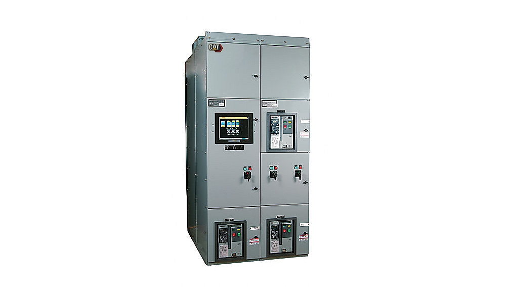
EGP (Emergency Generator Paralleling) switchgear is used for paralleling multiple generators that are not directly connected to a utility source.
| Technical Summary | |
| Configuration | Configurable PLC based switchgear capable of controlling and monitoring multiple generator sets, tie and load breakers in conjunction with downstream transfer switches for standby or emergency applications |
| Modes of Operation | Multi-unit Island and multi-unit standby mode with optional redundant controls and components. |
| Application | LV and MV (208V - 38 kV) |
| Generator Protective Devices | |
| ANSI Protective Devices | 15/25, 27/59, 81 O/U, 32, 40, 50, 51 |
| Environmental Parameters | |
| Certifications | IBC, CBC, UBC & OSHPD Certified |
| Control Panel Enclosure | NEMA 1 or NEMA 3R Freestanding Construction |
| Operating Temperature | 0°C to 50°C |
| Storage Temperature | -20°C to +60°C |
| Low Voltage Standards | NEMA SG-5, CSA, ANSI C37.51, ANSI C37.20.1, UL 1558 or UL 891, NFPA 110, NFPA 99 and NFPA 70 |
| Medium Voltage Standards | NEMA SG-5, ANSI / IEEE C37.20.2, CSA-C22.2 No. 31-M89, EEMAC G8-3.2, NFPA 70, NFPA 99 and NFPA 1110 |
EGP Switchgear
- High Speed Supervisory Network
- Automatic Start/Stop
- Automatic “Dead Bus” Coordination
- Programmable Load Shed / Load Add Functions
- Networked Engine Communications
- Generator Protection
- Engine Tuning
- Mode Selection
- Selectable Auto/ Manual Control
- Password Protection for Protective Settings and Setup
- Load/No Load Test
- Touch Screen (HMI) Display
- NFPA 99/110 Compliant Alarm
- Annunciation with Audible Horn
- Engine Control mimic Screen with gauges for RPM, DC Battery Voltage oil Pressure, Engine Coolant temperature, Engine Hours, Number of starts
Standard Equipment:
-
- Egp Switchgear
-
- Choice of 19” Surface Acoustic Wave Color or 15” Resistive Color Touchscreen
- Emergency Stop Button for each generator
- Instant Auto Switch
- Generator Demand Priority Control
- Audible Alarm & Horn Silence Button
- Circuit Breaker Control Switch with Indicators
Optional Equipment:
-
- Data Table Interface
-
- * Accomodates interface with a building management system for monitoring all system parameters via Modbus RTU or TCP
-
- Supplemental Hardware Synchronization Check Relay (ansi 25 Device)
-
- * Provides additional discrete synchronization protection
-
- Remote Power Monitoring System
-
- * To monitor breaker status, alarms, metering and other operating parameters


